Clamp
Configuration and bearing capacity are determined according to technical requirement. The product can be used in all kinds of industry.
Description
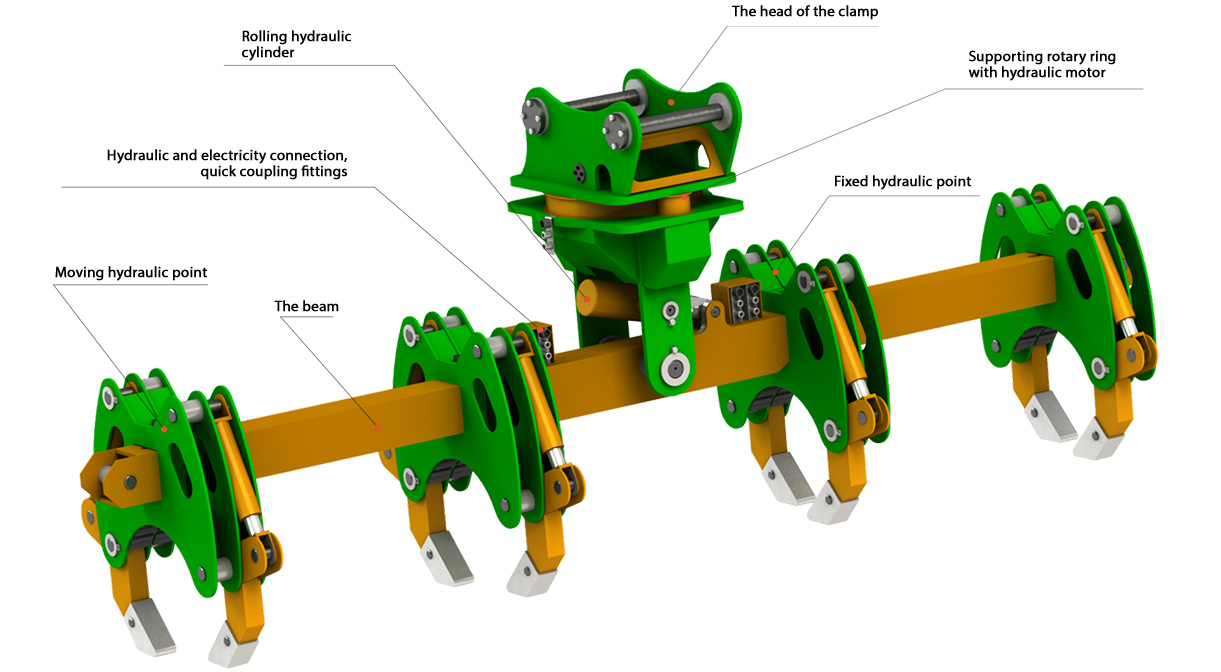
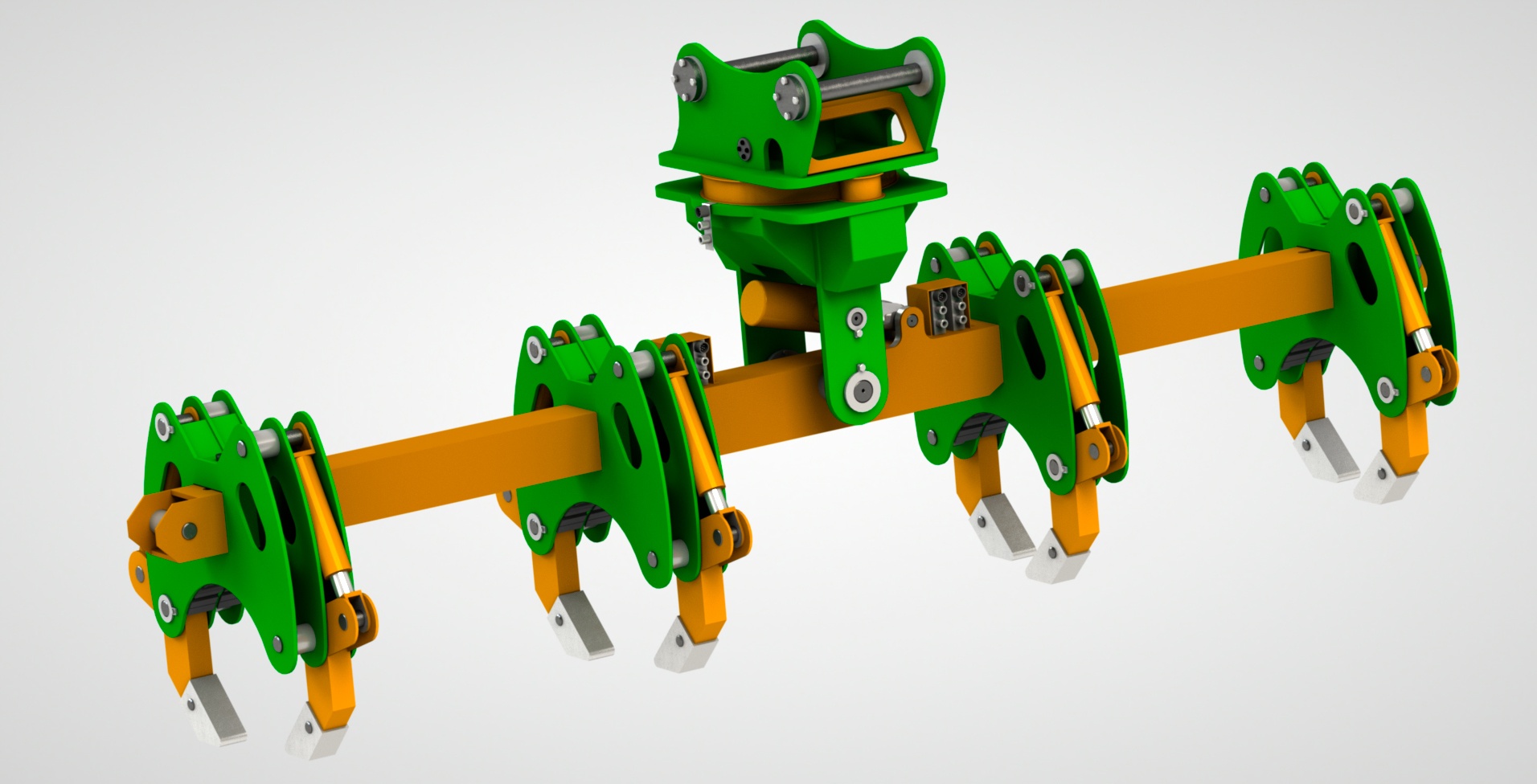
The hydraulic clamp is used for lifting and lowering of oil and gas pipelines and consists of 3 main units:
1. The head of the clamp
Device for combine attachment - a metal structure from sheet metal with lateral components for combine attachment.
Supporting rotary device. Bearing element - able to support loads of products and to move cargoes, to rotate on axis.
Quick coupling fittings - are mounted on 2 sides of the product to connect the issued electricity and to discharge/pressure the hydraulic system.
Rotating mechanism - 2 gear wheels (rolls), that make rotations and rotate the supporting rotary device applying hydraulic motors.
The hydraulic cylinder, linked with beam using pins, is mounted to provide rolling in the bottom part of the head.
2. The beam
Welded space structure from 3 to 6 meters in length.
From 2 to 4 universal cranks are attached on the beam with a square section using pins.
Cranks near the head are permanently attached.
Cranks near the edges have speed 400 mm applying hydraulic cylinder, that is installed inside the frame.
Quick coupling fittings in quantity of 4 pcs for each crank are installed on the frame.
3. Crank
Univelsal cranks can work independently or in pairs.
This universal crank is able to lift the pipe from Ø108 to Ø530 from soil without preliminary spudding.
Constructure consists of 2 off-centred points. Each point is actuated by the hydraulic cylinder.
The pipe is fixed by compressing with the points to the bottom part of the crank. Pressing force is registered with the sensors to prevent the collapse.
Configuration